Is lithium battery safe?
2026-01-10 16:51:59

Is lithium battery safe?
The Correct Charging Method for Lithium Iron Phosphate Batteries
Which has the longest lifespan: graphene, sodium batteries, lithium batteries? Why is the lithium iron phosphate battery recommended?
How long does the service life of lithium iron phosphate batteries typically last?
The charging management of lithium iron phosphate batteries directly affects their performance and lifespan: precise voltage and current matching, strict control within the optimal temperature range of 20-35°C, and the adoption of a three-stage intelligent charging strategy, combined with the BMS system to achieve safe fast charging. Mastering these core technologies can extend the battery lifespan by over 30%.
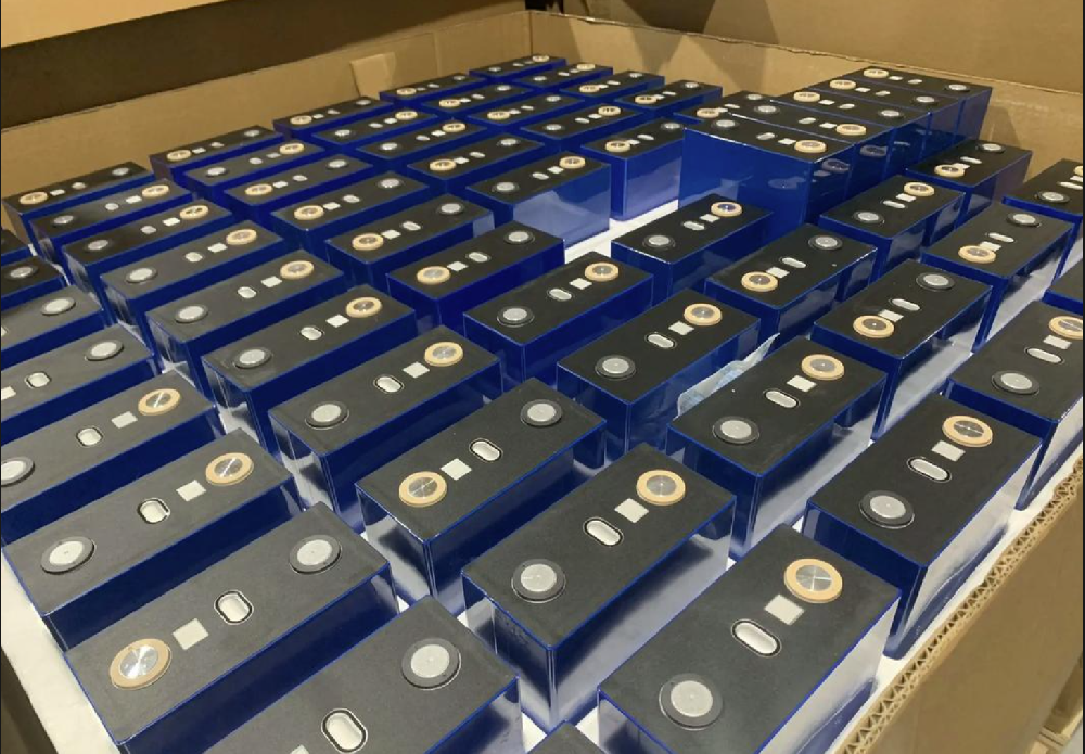
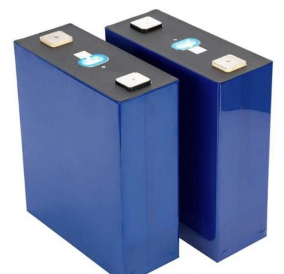
Lithium iron phosphate batteries (LiFePO4) are the representatives of the new generation of lithium-ion batteries, with their outstanding safety performance, extremely long cycle life, and environmental-friendly characteristics, being widely used in new energy vehicles, energy storage stations, communication base stations, and other fields. The olivine crystal structure of the battery endows it with unique thermal stability, maintaining structural integrity even under extreme conditions such as overcharging and short circuit, making it a benchmark product in the field of power batteries. However, the correct charging method directly affects the performance and lifespan of the battery, and improper operation may lead to accelerated capacity degradation and increased safety risks. This article will systematically analyze the key charging technologies of lithium iron phosphate batteries and provide practical guidance schemes based on actual application scenarios.
1. Charging Equipment Scientific Selection Criteria
1.1 Voltage Matching Principle
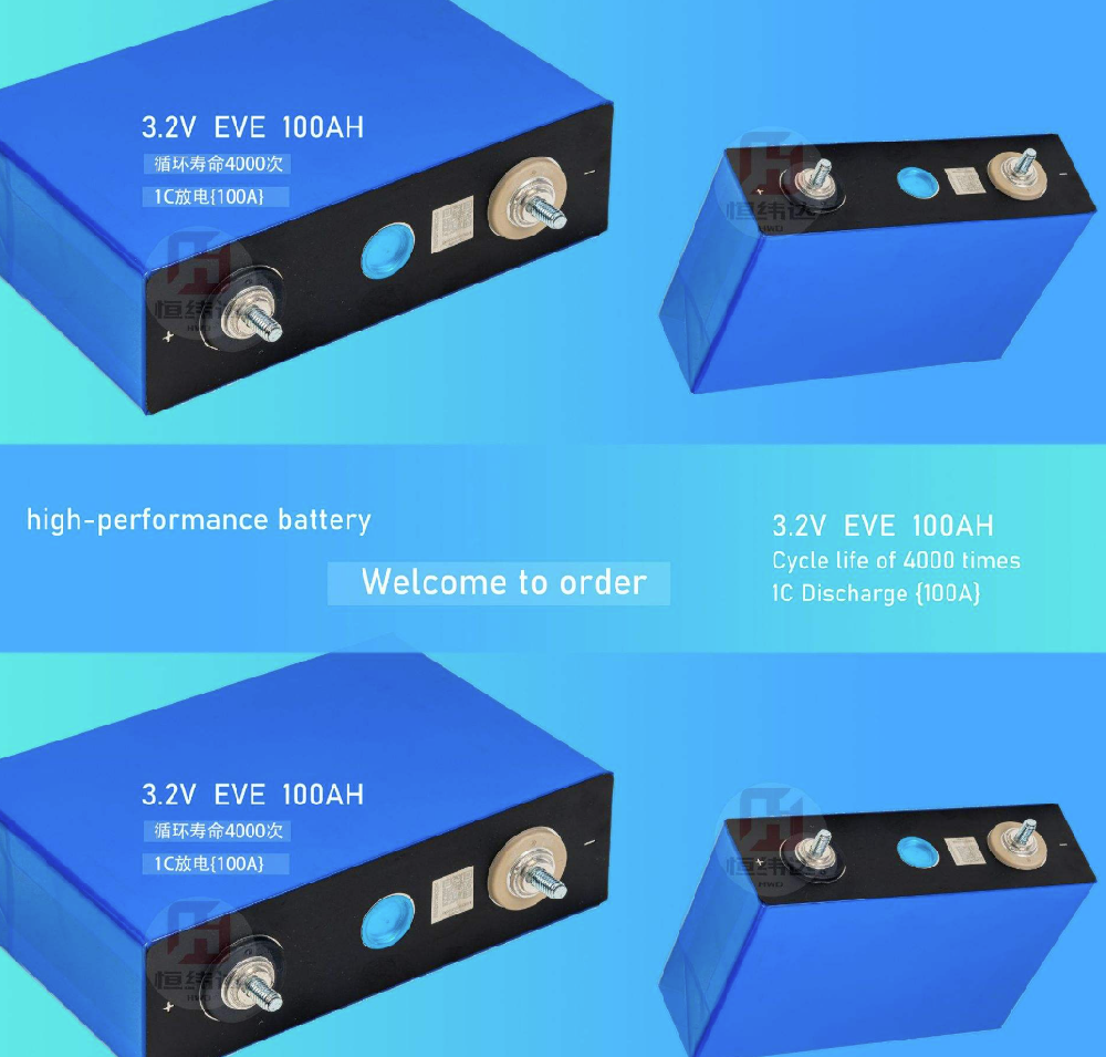
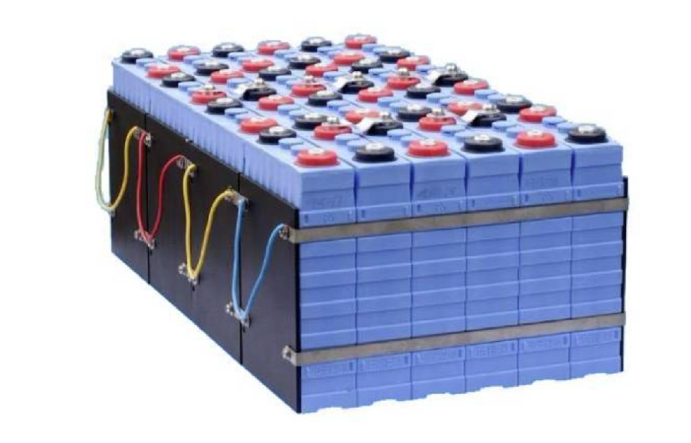
The nominal voltage of a single lithium iron phosphate battery is 3.2V, and the charging cut-off voltage is typically set in the range of 3.65V ± 0.05V. When forming a battery pack, the total voltage must be calculated based on the number of series connections:
• 4 cells in series (4S) form a 12V system (nominal 12.8V, cut-off 14.6V)
• 8 cells in series (8S) form a 24V system (nominal 25.6V, cut-off 29.2V)
• 16 cells in series (16S) form a 48V system (nominal 51.2V, cut-off 58.4V)
When choosing a charger, special attention should be paid to:
• Output voltage accuracy should be controlled within ±1%, avoiding voltage drift that leads to overcharging
• Have a multi-stage charging curve (precharge - constant current - constant voltage - floating charge) adjustment function
• Prioritize the use of intelligent chargers with BMS communication interfaces
1.2 Current Capacity Matching
The selection of charging current should balance efficiency and lifespan:
• Standard charging current (0.2C - 0.3C): For a 100Ah battery pack, a recommended charging current of 20 - 30A is recommended
• Quick charging current (≤ 1C): Requires support for fast charging protocols by the battery BMS
• Charging current in low-temperature environments should be reduced to below 0.1C
It is recommended to configure a charging current meter to monitor the charging power (voltage × current) in real time, avoiding exceeding the maximum allowable charging power of the battery pack (usually 0.5 - 1 times the rated capacity)
II. Precise Control of Environmental Parameters
2.1 Temperature Management Strategy
The environmental temperature directly affects the electrochemical reaction rate and internal resistance, thereby determining the charging efficiency and safety:
• Optimal operating range: 20℃ - 35℃. At this temperature, the internal resistance of the battery is the lowest and the charging acceptance ability is the best.
• Low-temperature compensation scheme:
o When the environmental temperature is less than 10℃, it is recommended to preheat the battery to 15℃ before charging.
o The charging current should be limited to below 0.1C to avoid lithium dendrite formation.
• High-temperature protection measures:
o Forced air cooling system: Maintain the temperature difference on the surface of the battery pack < 5℃.
o Temperature sensor layout: Key monitoring points should include the middle of the battery module and the outlet of the heat dissipation channel.
2.2 Humidity Control Specifications
• Relative humidity should be maintained within the range of 30%-60%RH for a long time.
• Protection for high humidity environment (>85%RH):
o Interface sealing treatment: Use IP67 waterproof connectors.
o Regular inspection: Clean the charging interface metal contacts with alcohol cotton swabs every quarter.
o Dehumidification plan: Configure an industrial dehumidifier to maintain the environmental dew point temperature below the battery surface temperature by 5℃.
III. Standardized Charging Operating Procedure
3.1 Pre-charging stage (battery voltage < 3.0V / single cell)
• Applicable scenarios: Batteries after long-term storage, recovery from over-discharge protection
• Key operation points:
o Use 0.05C microcurrent for activation
o Continuously monitor voltage changes. When the voltage rises to 3.0V, transfer to the standard charging process
3.2 Constant current fast charging stage
• Current setting: According to BMS restrictions, usually 0.2C - 0.5C
• Termination conditions: When the battery voltage reaches 3.6V / single cell, it ends
• Important precautions:
o For every 1℃ increase in battery surface temperature, the charging current should be reduced by 0.01C
o Regular battery balancing: Start balancing when the voltage difference between individual cells exceeds 30mV
3.3 Constant voltage floating charge stage
• Voltage setting: 3.65V / single cell ± 0.02V
• Termination conditions: Charging current drops to 0.02C
• Key control points:
o Float charge time does not exceed 2 hours
o Use stepwise voltage reduction method: Reduce 0.05V every 30 minutes until the voltage reaches 3.6V
3.4 Charging termination judgment
• Dual protection mechanism:
1. Time-based protection: Set the maximum charging time (capacity / current × 1.2 coefficient)
2. Negative increment (-ΔV) detection: Terminate when the voltage drop exceeds the set threshold
• The intelligent charger should have:
o Self-check function for temperature sensor failure
o Alarm for abnormal charging curve (such as voltage fluctuation > 0.1V/min)
IV. Maintenance-based Charging Management Scheme
4.1 Long-term Storage Management
• Voltage Control for Storage:
o Short-term (1-3 months): Maintain 50%-60% SOC (approximately 3.3V per cell)
o Long-term (>3 months): Reduce to 30% SOC (approximately 3.2V per cell)
• Regular Maintenance Cycle:
o Conduct a complete charge-discharge cycle every 3 months
o For every 10°C increase in storage environment temperature, the maintenance cycle is shortened by 50%
4.2 Health Status Monitoring
• Key Parameter Tracking:
o Internal Resistance Changes: Need to monitor when internal resistance increases by 30%
o Capacity Degradation: Consider retirement when actual capacity is less than 80% of rated capacity
• Diagnostic Tool Configuration:
o Battery Internal Resistance Tester (accuracy ±0.1mΩ)
o Infrared Thermal Imaging Instrument (frame rate ≥30Hz)
4.3 Special Scenario Handling
• Salt Spray Environment Protection:
o Coat charging interface with three-layer anti-corrosion paint
o Conduct contact resistance test monthly (should be <5mΩ)
• Vibration Conditions Response:
o Use flexible connection cables
o The vibration acceleration during charging should be controlled below 0.5G
V. Safety Risk Prevention System
5.2 Emergency Handling Procedure
1. Immediately cut off the main circuit power supply
2. Start the ventilation system (ventilation frequency ≥6 times/hour)
3. Use infrared temperature measurement instrument to monitor the battery group temperature
4. Start the gas fire extinguishing device when the temperature is >60°C
5. Conduct 48-hour static observation after the accident
VI. Prospects for Frontier Technology Application
6.1 Wireless Charging Technology
• Magnetic Resonance Wireless Charging:
o Transmission distance can reach 10cm
o Efficiency >90% at 100kHz working frequency
• Application Scenarios: AGV vehicles, warehouse robots, etc. for automated equipment
6.2 Intelligent Charging Algorithm
• Dynamic Current Regulation:
o Fuzzy control algorithm based on SOC and SOH
o Charging efficiency is improved by 15%-20%
• Cloud Platform Management:
o Remote firmware upgrade
o AI analysis and prediction of charging data
Conclusion: Establish a full life cycle charging management system
The charging management of lithium iron phosphate batteries has evolved from simple energy replenishment to a complex system engineering. Through scientific selection, precise temperature control, intelligent monitoring, and preventive maintenance, the maximum performance of the batteries can be achieved. In the future, with the improvement of computing power of battery management chips and the integration of Internet of Things technology, the charging process will become more intelligent and personalized, providing a solid foundation for the construction of the energy internet. Users should establish a "select-use-maintain-repair" full cycle management awareness, allowing lithium iron phosphate batteries to continue creating value in a safe and efficient state.
